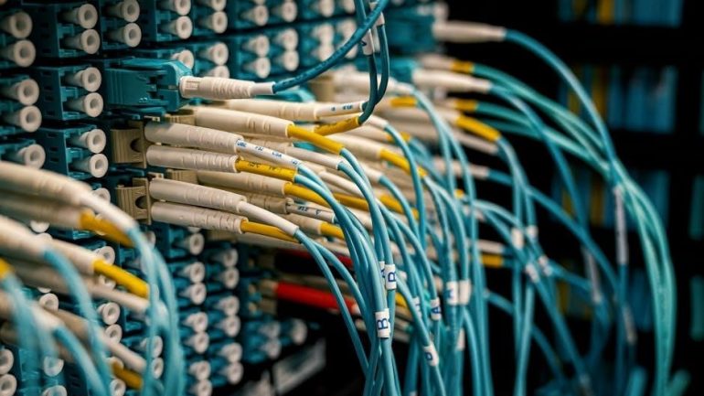
Managing internal wiring requires precision to ensure seamless connectivity. Following established patterns helps users organize their systems. These guidelines prevent errors and facilitate easier troubleshooting when managing various connectivity setups within modern digital environments and systems.
Importance of Standardization
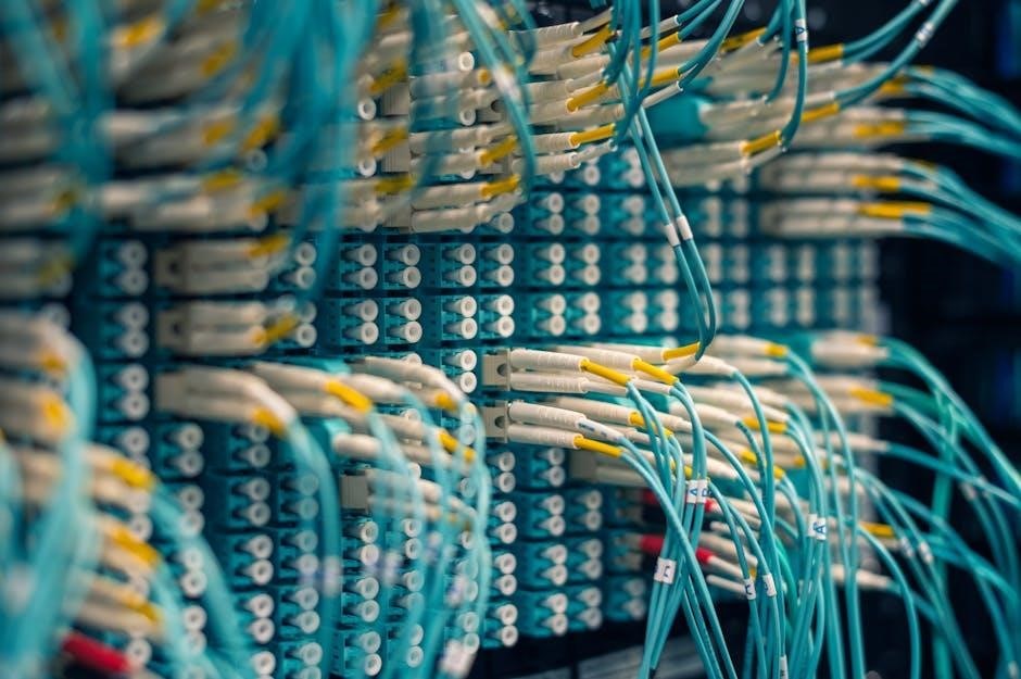
Standardization in cabling ensures that any technician, regardless of their training location, can identify the purpose and layout of a connection immediately. Without universal rules, every installation would be a unique puzzle, making maintenance an absolute nightmare for IT professionals. When everyone follows the same blueprint, the risk of miswiring decreases significantly, which protects expensive hardware from potential electrical mismatches or signal degradation. Furthermore, consistency allows for rapid scaling of infrastructure. When a company grows and needs more ports, new additions integrate perfectly with existing lines because the logic remains identical across the entire building. This uniformity reduces the time spent on diagnostic tests and eliminates guesswork during critical outages. By adhering to global norms, organizations ensure that their physical layer is robust and predictable. This reliability is the foundation of all high-speed data transmission, as it guarantees that signals travel across the copper pairs in a known and controlled manner. Ultimately, relying on these shared protocols transforms a chaotic tangle of wires into a structured system that is easy to manage, audit, and upgrade over time. This creates long term stability.
Common Types of Network Cables
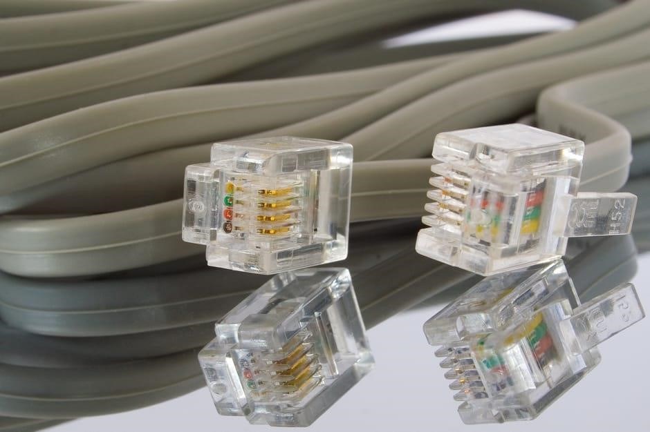
Selecting the right medium is crucial for optimizing data transfer rates and reducing interference. Unshielded Twisted Pair (UTP) is the most frequent choice for residential and small office environments due to its flexibility and lower cost. However, in areas with high electromagnetic interference, Shielded Twisted Pair (STP) is preferred to protect signal integrity. Category 5e cables are common for basic gigabit networks, providing a reliable balance of speed and affordability. For those requiring higher performance, Category 6 cables introduce a plastic separator to reduce crosstalk between pairs, allowing for faster transmission over shorter distances. Moving further up, Category 6a provides an augmented experience, supporting ten gigabit speeds across a full hundred meters. For extreme environments or data centers, Category 7 and Category 8 offer superior shielding and massive bandwidth capabilities to handle intense traffic loads. Each category differs in terms of frequency support and construction materials, ensuring that users can choose a cable that matches their specific hardware capabilities and environmental needs. Understanding these variations allows for a scalable network that meets the demands of modern high-speed internet and internal communication systems.
Understanding the T568A Wiring Standard
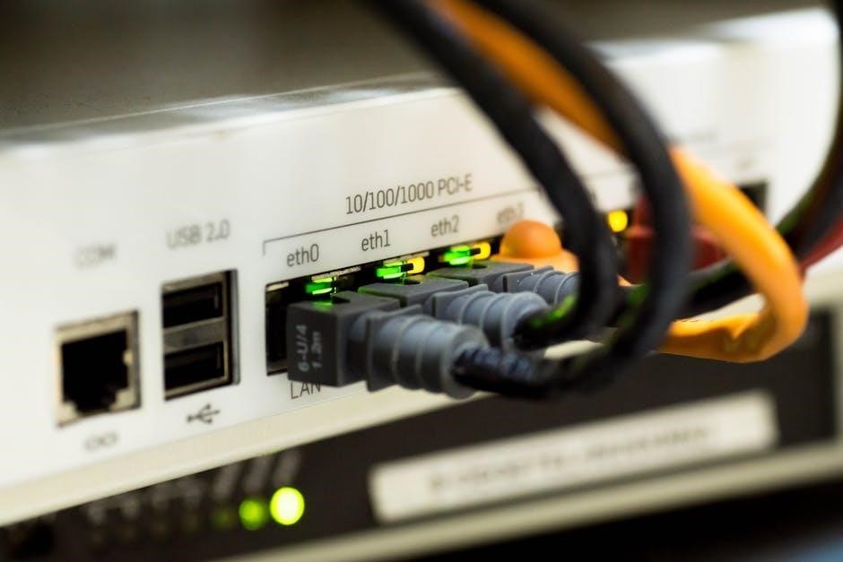
This particular configuration represents a primary method for terminating twisted pair cables. It provides a consistent framework for technicians to follow while preparing connections for various networking equipment and wall jacks across many different installations globally.
T568A Color Sequence Breakdown
The specific arrangement for this standard follows a strict order to ensure electrical signals transmit correctly. Starting from pin one, the first wire is white-green, followed immediately by the solid green wire. The third position is reserved for the white-orange strand, while the fourth pin utilizes the solid blue conductor. Moving to the fifth position, we find the white-blue wire, which is followed by the solid orange wire at pin six. Finally, the seventh pin is the white-brown wire, and the eighth pin concludes the sequence with the solid brown wire. This precise order is critical for maintaining signal integrity and preventing interference within the twisted pair architecture. By adhering to this layout, technicians ensure that the physical layer of the network operates efficiently. When looking at a connector with the gold contacts facing upward and the clip facing away, the sequence starts from left to right. This systematic approach eliminates guesswork during the termination process, allowing for rapid deployment and consistent results across all network hardware and infrastructure installations throughout the entire building or facility. This method is very highly reliable.
When to Use T568A
Selecting this particular wiring scheme is often a matter of regional preference or specific project requirements. In many residential settings, this configuration is frequently implemented because it aligns better with older telephone systems. Additionally, various government contracts in the United States traditionally mandated the adoption of this standard for their internal infrastructure. If you are working within an existing facility that was originally wired using this method, it is imperative to maintain consistency across all new terminations. Mixing standards within a single environment can lead to confusion for future maintenance teams and potential connectivity failures if not documented correctly. While modern installations often lean towards the alternative, knowing when to apply this specific layout is essential for technicians handling legacy hardware. It ensures that the physical cabling remains uniform and compliant with the original specifications of the building. By choosing this path, professionals can avoid costly rewiring projects and ensure that the existing network architecture continues to function without interruption. It is fundamentally about maintaining harmony with the existing physical layer to guarantee that data flows smoothly across the entire localized environment.
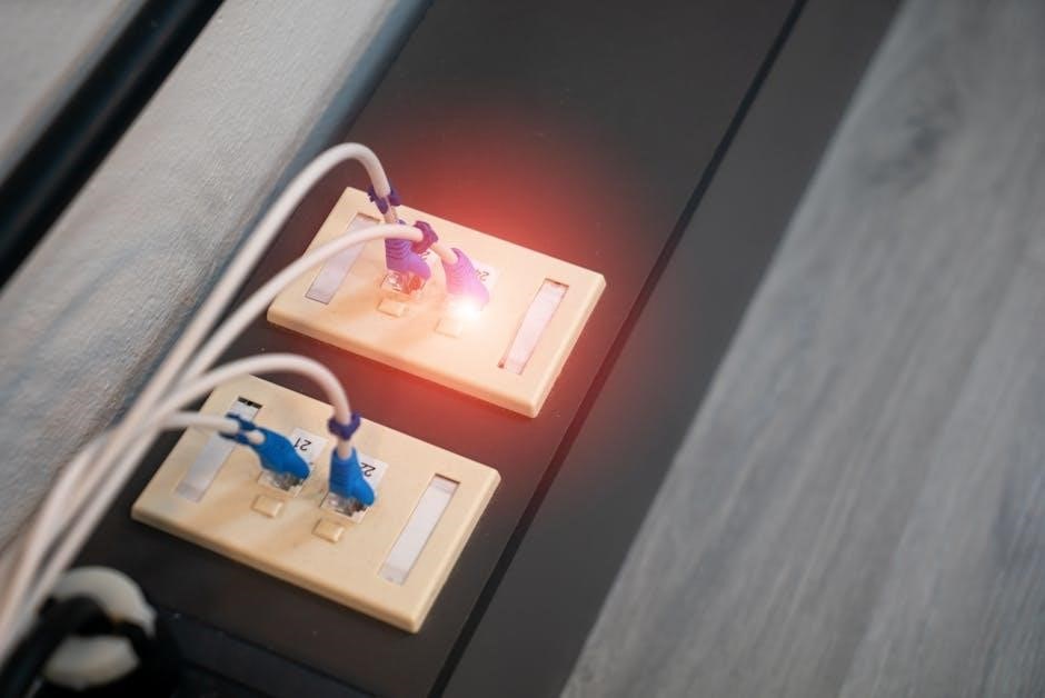
Understanding the T568B Wiring Standard
This widely adopted arrangement serves as a primary benchmark for technicians throughout the globe. It ensures that physical connections are consistent, allowing hardware from different manufacturers to communicate effectively within any professional local area network infrastructure.
T568B Color Sequence Breakdown
The T568B standard follows a specific order of wires to ensure high performance and reliability. When looking at the connector with the gold pins facing up, the first wire is white-orange, followed by solid orange. The third position is filled by white-green, while the fourth slot holds the solid blue wire. Moving further, the fifth wire is white-blue, and the sixth is solid green. The sequence concludes with white-brown in the seventh spot and solid brown in the eighth position. This precise arrangement is critical because it maintains the twisted pair integrity required to minimize electromagnetic interference and crosstalk. Technicians must align these colors perfectly before crimping the connector to avoid connectivity failures. Each pair is twisted for a reason, and adhering to this exact sequence ensures that the electrical properties of the cable are preserved across the entire link. By meticulously following this pattern, installers can be confident that the physical layer of the network is correctly established, allowing for maximum data throughput and stability across the infrastructure without any signal degradation or intermittent connection issues. This method is most popular.
When to Use T568B
This specific wiring arrangement is the most widely adopted standard in modern commercial networking environments, particularly throughout North America. You should implement this configuration when you are installing new infrastructure in a business setting where compatibility with existing hardware is paramount. Since most factory patch cords follow this layout, using it for your wall jacks and patch panels ensures a seamless and consistent environment. It is the preferred choice for professionals who want to adhere to the most common industry practice, reducing the likelihood of confusion during future maintenance or upgrades. If you find that the current building wiring already utilizes this pattern, you must continue using it to maintain uniformity across the entire facility. Mixing different standards on the same link can lead to connectivity issues, so sticking to this single approach is highly recommended for stability. This method is ideal for standard ethernet installations where specific legacy requirements are not present. By choosing this standard, you align your physical layer with the majority of global installations, ensuring that any standard equipment will function correctly without needing specialized adapters or mods.
Straight-Through vs. Crossover Cables
Choosing between these two cable types depends on the devices you are connecting. One links different devices, while the other connects similar hardware. Understanding this core distinction is vital for establishing a functional local area network.
How to Create a Straight-Through Cable
To assemble this specific type of connection, start by removing the outer jacket from both ends of the cable. Carefully untwist the internal pairs to expose the individual colored wires. Arrange these wires in a linear fashion, ensuring that both ends follow the exact same wiring sequence. This uniformity is what defines the linear configuration, allowing signals to flow directly from one pin to its matching pin on the opposite side. Once the wires are aligned, trim them evenly so they fit snugly into the connector. Slide the arranged wires into the RJ45 plug, pushing them all the way to the front edge. Verify that each wire sits in its correct slot and that the jacket is gripped by the connector for stability. Finally, use a tool to secure the plug firmly. This process ensures a reliable physical link between disparate hardware. By maintaining identical pinouts at each extremity, you create a path that is compatible with most modern networking equipment. Precision during the alignment phase is critical to avoid connectivity failures or signal degradation during data transmission across the entire link.
How to Create a Crossover Cable
To build a crossover cable, you must implement a specific arrangement where the transmit and receive pairs are swapped between the two ends. Begin by stripping the outer insulation from both cable extremities. On the first end, arrange the internal wires according to one standard protocol. For the second end, you must swap the orange and green pairs. Specifically, the pins that typically transmit data on one side must connect to the pins that receive data on the other side. This configuration allows two similar devices, such as two computers or two switches, to communicate directly without needing a hub. Ensure the wires are perfectly straight and trimmed before inserting them into the RJ45 connectors; Push the wires firmly to the end of the plug and verify the sequence visually. Once aligned, secure the connector with the appropriate pressing device to ensure a solid electrical connection. Confirm that the jacket is held firmly within the plug to prevent wires from pulling out. This specific crossover method is essential for legacy hardware that lacks automatic detection capabilities for cable types during the handshake.
Tools Needed for Cable Termination
Properly terminating network cables requires a set of specialized equipment. These instruments ensure that every connection is secure and meets industry standards. Having the right gear prevents physical damage and guarantees fast data transmission performance quality.
Crimping Tools and Strippers
A professional crimping tool is an essential device used to attach connectors to the ends of a network cable. It compresses the metal pins of the RJ45 connector into the individual copper wires, creating a permanent electrical connection. Without a high-quality crimper, the pins might not penetrate the insulation properly, leading to intermittent signals or complete connectivity failure. It is crucial to select a tool that fits the specific connector type being used to ensure a tight seal. Complementing the crimper is the cable stripper, a tool designed to remove the outer plastic jacket without damaging the internal twisted pairs. Using a dedicated stripper is far safer than using scissors or knives, which often nick the inner insulation. A clean strip allows for easier arrangement of the internal wires before they are inserted into the plug. Together, these two tools form the foundation of physical layer installation. By mastering their use, technicians can produce clean, professional terminations that withstand physical stress over time. These manual tools are indispensable for any technician working with physical infrastructure, ensuring every single connection is mechanically sound.
Cable Testers for Verification
After finishing the termination process, verifying the physical integrity of the connection is a critical step. A network cable tester is used to confirm that every single wire is correctly mapped from one end to the other. These devices typically consist of a master unit and a remote unit. By plugging both ends of the cable into these components, the tester sends electrical signals through each pin. If the lights blink in the correct sequential order, the cable is wired correctly. However, if a light skips or flashes out of sequence, it indicates a miswire or a broken connection. Advanced testers can even detect “shorts,” where two wires are touching, or “opens,” where a wire is completely severed inside the jacket. Using a tester saves an immense amount of time by eliminating the guesswork involved in troubleshooting. Instead of wondering why a computer cannot connect to the switch, a quick test provides an immediate answer. This verification process ensures that the installation meets professional standards and operates at full speed without any packet loss or connectivity drops. It provides absolute certainty now.
Finding a Network Cable Code Color PDF
Searching online for a downloadable reference guide allows technicians to keep essential diagrams handy. These digital files are often available on manufacturer websites or specialized technical forums, providing a quick way to access very vital information.
Key Features to Look for in a PDF Guide
A high-quality reference document should prioritize visual clarity above all else. Look for high-resolution images that clearly illustrate the orientation of the connector, ensuring that the pins are easily identifiable. A great resource will feature a side-by-side comparison of different layouts, allowing for a quick visual check without needing to flip through multiple pages. It is also beneficial to find files that are optimized for mobile viewing, as technicians often access these guides on smartphones while working in server rooms or tight spaces. Additionally, ensure the document includes a clear legend that defines each color used in the diagrams to avoid any ambiguity. Check if the file is in a universal format like PDF to ensure compatibility across all devices. A well-organized layout with a table of contents makes navigation efficient. Finally, verify that the source is a reputable industry authority to ensure the diagrams are accurate and current. These elements combined make a digital manual an indispensable tool for anyone performing wiring tasks, providing a reliable source of truth that reduces the risk of costly installation errors during the setup process.